Module TPS - 3351
Digital Electronics Training System
Technical Characteristics
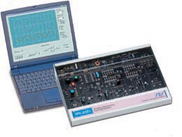
The trainer is enclosed in a metal case, which has a wide experiment platform printed circuit board (22cm x 35 cm). This ensures easy handling and good visibility of the components.
The components are located on the board which has a silkscreen print of the analytical circuit and component symbols. The central part of the experiment board includes all the circuit block drawings and all the hands on components and test points.
The protected components are located on the circuit board, clearly visible to the student and protected by a sturdy transparent cover.
The system includes a built in power supply with +12V, +5V, variable DC voltage, and AC voltage outlets. An included low voltage external AC power adapter feeds the system.
The system includes:
• CMOS/TTL logic probe
• 8 switches
• 8 LEDs
• Gates: AND, OR, NOT, NAND, NOR, XOR
• Decoders
• Multiplexers
• Adders
• Push-button switches with debouncing circuit
• 4 JK-FF for Flip-Flop applications
• 2 Up/Down counters.
• 2 parallel I/O shift registers
• 555 Clock generator
• ADC circuit
• DAC circuit
• SES Lab unit with analog signal generator / 8-channel digital
generator and two channel oscilloscope / 8-channel logic analyzer, which
communicates with a PC for the scope/logic analyzer display and controls
the signal generator
• PC Software (Optional)
This course introduces the student to digital electronics: families of logic devices, logic and combinatorial circuits, sequential logic circuits, and integrated digital systems including A/D – D/A conversion.
Description
The system is stand-alone, containing all the necessary electronics components needed for performing hands-on experiments.
The experiment area is in the central part of the trainer including circuit drawing, test points, and peripheral outputs and inputs.
The circuit board contains visible component circuits protected by a sturdy transparent cover.
The system includes a built in power supply with +12V, +5V, and variable DC voltage.
The system includes a CMOS/TTL logic probe and the SES Lab unit with analog and 8 channel digital signal generator and 8-channel logic analyzer. It also includes a two-channel oscilloscope, which communicates with a PC to control the signal generator and display the scope and the logic analyzer's signals.
The built in signal generator also can be operated manually, controlled
by the embedded micro-controller for sine/triangle, digital/analog signals.
Experiments
This system enables the student to perform several experiments and covers the following topics.
• Logic gates
• Logic gate families
• AND gates
• OR gates
• NOT gates
• Combination of logic gates
• Logic levels
• CMOS logical circuits
• TTL NAND gate
• TTL inverter gate
• Combinations of logic device families
• Boolean algebra
• Karnaugh maps
• NAND gates and NAND equivalent circuits
• NOR equivalent circuit and NOR
• XOR gates
• Digital comparator
• Decoders
• Multiplexers and Demultiplexers
• Half adder and full adder
• ALU – Arithmetic - logic unit
• RS flip – flop
• Latches
• JK flip-flop
• D flip-flop
• Registers and shift registers
• SIPO and PISO
• Asynchronous JK counter
• Synchronous circuits with D flip-flops
• Timing circuits with 555
• Binary ripple counter and synchronous counter
• Analog signal to digital signal conversion
• Fault diagnosis
the system