Module TPS - 3331
Analog Electronics Training System
Technical Characteristics
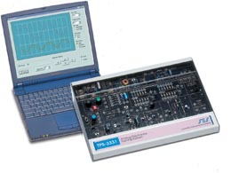
The trainer is enclosed in a metal case, which has a wide experiment platform printed circuit board (22cm x 35 cm). This ensures easy handling and good visibility of the components.
The components are located on the board which has a silkscreen print of the analytical circuit and component symbols. The central part of the experiment board includes all the circuit block drawings and all the hands on components and test points.
The protected components are located on the circuit board, clearly visible to the student and protected by a sturdy transparent cover.
The system includes a built in power supply with +12V, +5V, variable DC voltage, and AC voltage outlets. An included low voltage external AC power adapter feeds the system.
The system includes
• Diodes
• Resistors and Potentiometers
• Zener Diodes
• Inductors and capacitors
• Bipolar Transistor circuits
• FET circuits
• Operational amplifier applications circuit
• Transistor power amplifier with speaker
• Linear Regulator circuit
• Switching Regulators circuit
• SESLab unit with two-channel scope and function generator, which
communicates with a PC to control the function generator and oscilloscope
display, including spectrum analysis
• PC software (Optional)
The system has an optional add-on troubleshooting card that communicates
with the instructor’s PC via the SESML network.
Using the multiple choices student exams, the student answers the exam
question with the trainer’s keyboard and display. The instructor
can build a database of students, classes, and exam answers and can monitor
the students’ exams.
This course introduces the student to analog electronics and covers topics such as voltage, current, resistors, measurements, electricity laws and circuits, diodes, diode circuits, transistor (Bipolar and FET) characteristics, transistor amplifiers, operational amplifier characteristics and applications, oscillators, filters, power amplifiers, power supplies, linear and switching regulators
Description
The system is stand-alone and contains all the necessary electronics components needed for performing hands-on experiments.
The experiment area is in the central part of the trainer including circuit drawing, test points and peripheral outputs and inputs. The circuit board includes visible component circuits protected by a sturdy transparent cover.
The system includes a built in power supply with +12V, +5V, and variable DC voltage.
The system includes the SES Lab unit with a two-channel oscilloscope and a function generator, which communicates with a PC to control the function generator and oscilloscope display, including spectrum analysis.
The built in function generator can also be operated manually, controlled
by the embedded micro-controller for sine/triangle, sweep/constant signals.
Experiments
This system enables the student to perform several experiments and covers the following topics.
• Basic transistor amplifiers
• Operational amplifiers characteristics and single supply methods
• Differential operational amplifier
• Adder operational amplifier
• Operational amplifier applications
• Inverting and non-inverting amplifiers
• Comparators
• Schmitt trigger, square wave generator
• Ohm’s law
• Series and parallel resistive circuits
• Kirchoff’s law
• FET amplifier
• PN junction and diode characteristics
• Diode circuits and applications
• Zener diode: characteristics and applications
• Low pass and band pass filters
• Bipolar transistors DC circuits and amplifiers
• FET transistors DC circuits and amplifiers
• RC oscillator
• Wien bridge oscillator
• Multistage amplifiers
• Non-inverting and unity gain operational amplifiers
• Bi-stage transistor amplifier
• Class A, B, C push pull amplifier
• B class amplifiers with MOSFET output
• AB class power amplifiers with bipolar transistors
• Summer and difference amplifiers
• Integrator and differentiator
• Power supply transformers, rectifiers, smoothing
• Linear regulators
• Step-down switching regulator
• Step-up switching regulator
• Inverter switching regulator
• Non-stabilized power supply
• Stabilization with transistor
• Stabilization with integrated circuit
• Fault diagnosis at a power amplifier
• Oscillator and fault diagnosis to filters
• Fault diagnosis